lpg-leak-detect-iot
LPG Leak Detector
There are already lots of projects built on top of the MQ family of sensors and also specifically the MQ6. In my case, the goal here was multifold:
- Work with a new sensor for me (MQ 6)
- Understand web hosting support inside a Node MCU
- Be able to create a named IoT device connected to the home network
- Try out the Debian app on Windows 10 which would run the client script talking to the named IoT device
This article comprises of the following sections:
- The MQ6 sensor
- System overview
- Detector code
- Script code
- Results
- Key learnings
About the MQ6 sensor:
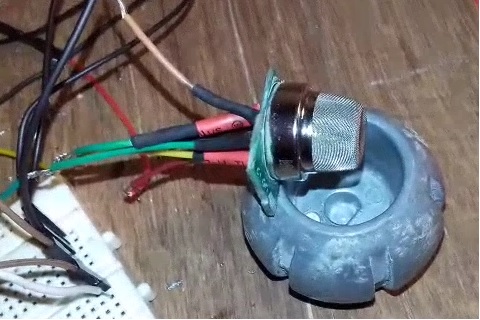
I did not buy this separately but I had one fixed to a commercial household LPG leak detector. That system was old and wasn’t working since quite some time. I had already salvaged parts of it for other things (battery charging circuit). I decided to desolder the MQ 6 and use it my own project. However, I wasn’t able to successfully desolder it so in the end, I just cut out the part of the PCB hosting the sensor. The pins were hardly visible but I managed to solder multicore wires to it and via a heatshrink assembly was able to reasonably protect those delicate connections. The MQ 6 does not have any polarity to its pins so you can decide which is which. Of course you need to respect the A, B and H pin identity but you can decide which is H+ & H-. This explains the working principles of all MQ series sensors. The sensor needs some settling time for its heater – first time use is 24 H but subsequent uses are a few minutes. The heater also has a good current draw (~150 mA); you must power it from an external power source and not from your microcontroller. I have not gone into details of connecting the sensor as many people have done that and it is available via a web search easily. Note that practically you would need to convert the analog OUT readings of the sensor to ppm (parts per million) concentration of the gas (I have not incorporated that in my code). My salvaged MQ6 is shown below resting on a steel bowl.
System Overview:
Goal was to design a system as shown in the figure below:
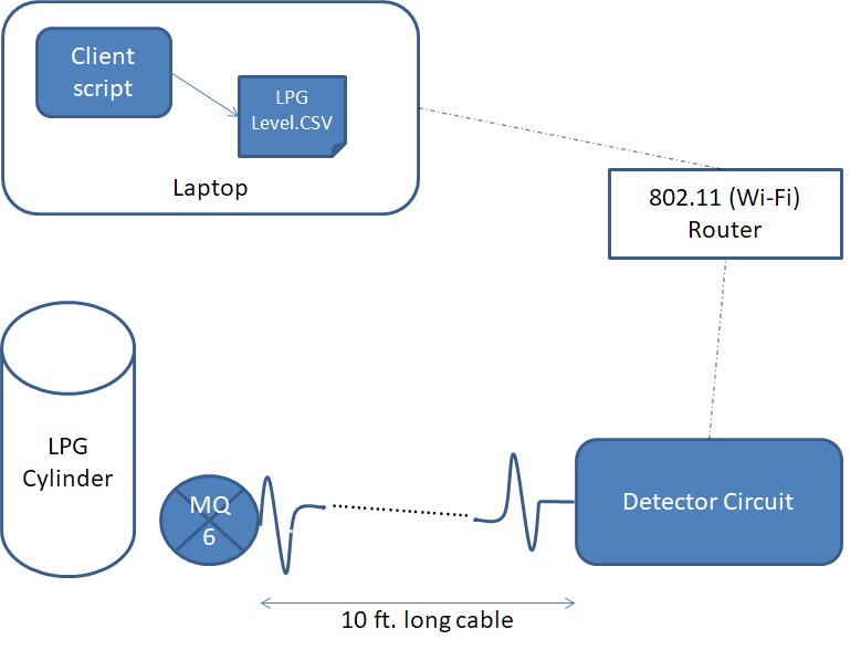
The sensor would be put in a compartment where the LPG cylinder resides. It needs to be as low as possible as the LPG gas itself is heavier than air and tends to collect at the bottom first, in case of any leakage. Considering safety and also the fact that this compartment is not easy to access frequently, I decided to lay a cable from the MQ6 to the Detector circuit. This also allows me enough flexibility to put the Detector where I wish to. I used extension cord cables and soldered them to the four pins of the MQ6 – A, B, H+ and H-. These cables entwined together (each with its own shielding), then lead into the Detector. I used cable ties to manage the cable bulk and avoid it spreading out and becoming snagged in something. The Detector overview is below.
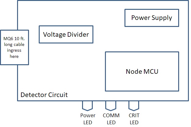
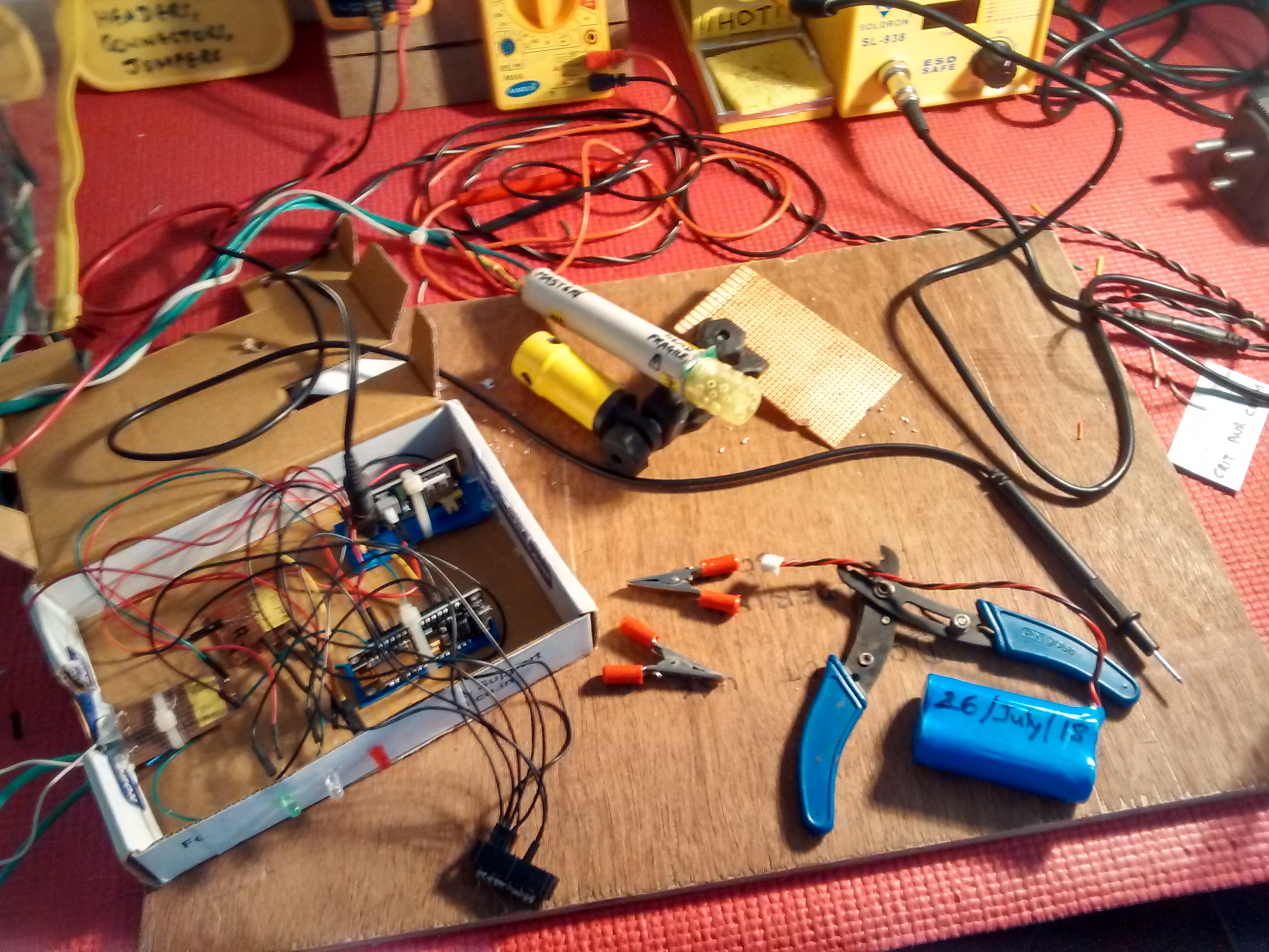
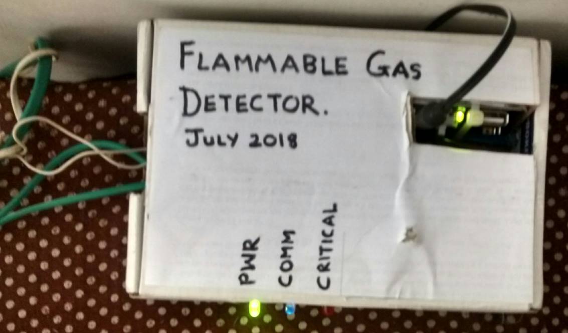
The MQ6 cable ingress is indicated. In addition there is a voltage divider to allow the Node MCU’s analog IN to measure the voltage level change due to gas levels. Apart from that, there is a power supply that supplies 3.3V to the Node MCU and 5V to the MQ6, each separate and independent. There are 3 LEDs; green LED indicates power to the system, a second blue LED blinks every time the Detector and the client script successfully communicate (COMM) and the third red LED lights up when the detected LPG level crosses a set threshold (CRIT). The circuit was first prototyped as a loose breadboard based system and a video and image is shown below. Note that the video shows the Node MCU powered off a battery but in the final circuit, I chose to run everything off a wall wart. Also the battery isn’t really connected if you look carefully. Everything was powered by a power module.
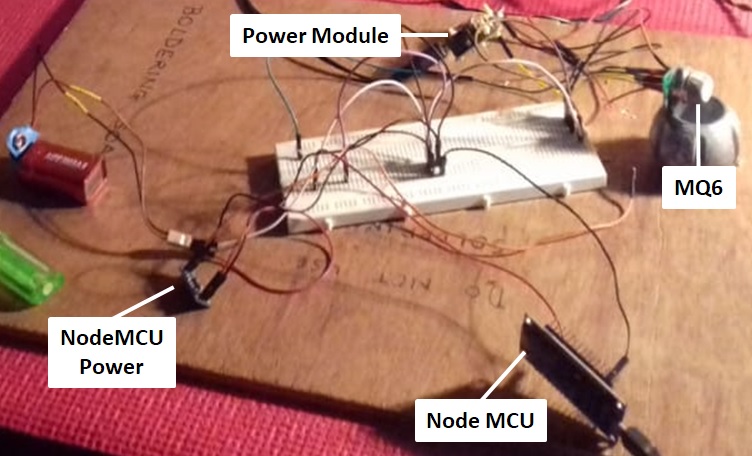
A video of the above setup:
The Node MCU is connected to an 802.11 router and is also hosting a simple HTTP based web server inside it. The code is explained later in this article. The Wi-Fi network that the Detector connects to is also connected to by a laptop. In this case, my laptop is running Win 10 and a Debian Linux Win 10 app is running on top of it. There is a python script running under Debian which periodically requests the LPG level from the Detector, over HTTP. The script is explained later in this article itself.
Detector Code:
This code runs in the Node MCU. Full source is available here. The code logic is as follows:
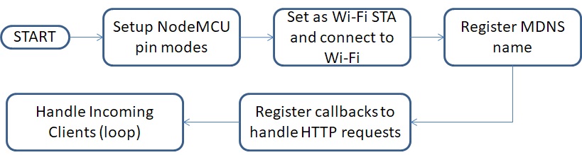
- Setup pin modes: Here we set the required pins as OUTPUT and also HIGH as needed. We also initialize Serial communications to be able to debug during development via a serial port.
- Set as WiFi STA and connect to WiFi: Node MCU will run in 802.11 station mode and connect to the specified router network.
- Register MDNS name: MDNS (Mobile DNS) allows us to name IoT devices and refer to them by that name always (as against remembering cumbersome IP addresses).
- Register callbacks: Since the Node MCU is running as a web server, we need to register callbacks to handle incoming clients. That is done here and also we finally start the web server service.
- Loop: All of the above is setup code that runs once after power up. The loop logic simply calls for handling clients. The NodeMCU framework takes care of handling the linking of each client HTTP request to the afore-registered callback handlers.
Python Client Script Code:
The client is pretty simple and written in python. The full source is here. The code logic is as follows:
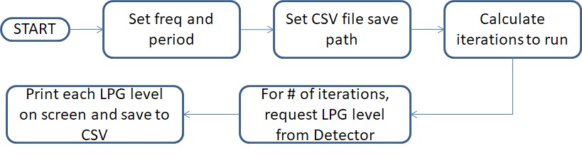
- Set freq and period: Set the HTTP request frequency (interval to request LPG level over HTTP from the Detector) and the period (total time to continue requesting for).
- Set CSV file path: Path to save the CSV file in. We can use this file to generate graphs and run analysis.
- Calculate iterations: calculate how many iterations the code shall loop for
- “For # …” and “Print each LPG…” this where we use the Requests library to query the Detector for the LPG level and also write it to disk.
Results:
Before we go into the results, here are some more pictures of my setup. The first one below shows the Detector system partly packaged into a cardboard box. The black part at the bottom of the image (below the LEDs) where many wires are routed is a header acting as a common ground plane:
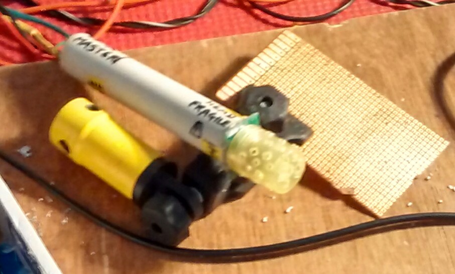
Here is a close-up of the MQ6 assembly itself. I have placed the MQ6 into a thick PVC pipe and topped it with a plastic cap having perforations. This is essentially to protect the MQ6.
Finally, a picture of the Detector box closed up. The green and white cables are the 10 ft cables going to the MQ6 assembly above.
The output was pretty good and relatable across readings and sessions. Here are the graphs of runs of a few hours. The raw CSV’s are available here.
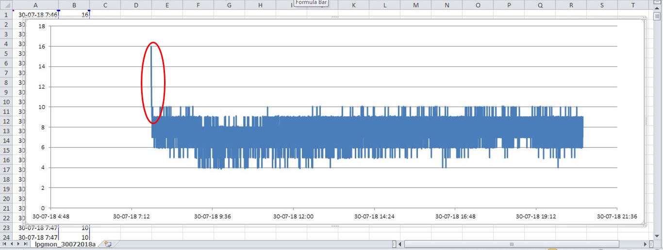
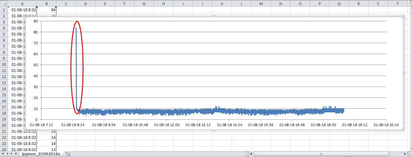
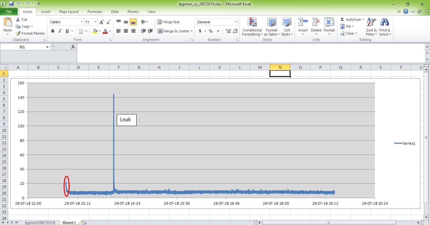
The large values (circled red) at the very start seen on the graph are the heater stabilizing. It takes a few minutes to do that and provide stable values. After that happens, the system is ready to detect. Below is a graph where leak detection was made. It is quite evident from the graph itself.
Key Learning:
- Current draw of your sensor is important, nay critical. You must find their peak values and nominal values. Taking this alongwith the projected current draw of the rest of your circuit helps you design the right power supply. Failure to do this will mean non-working / glitchy readings at best and a blown component / microcontroller at worst.
- DC voltage drops as the length of your wire increases. How much it drops is usually a function of the wire gauge and length and other factors. You would be well advised to theoretically calculate this before hand to avoid nasty bugs later. In my case here, I did do the calculation and it predicted minimal drop so I did not do anything special to counter it. Empirically, I measure that a +4.86V into the MQ6 at the Detector end resulted in a +4.81V at the MQ6 end.
- MQ6 is also sensitive to alcohol and cooking smoke and this affects readings. Always minimize their occurrence near the sensor.
- Common ground planes are obviously critical, especially when you have more than a few components in your circuit. For prototyping projects like these, I’ve found that shorting all pins of a standard header and then routing all your grounds to it is a good way to neatly manage a common ground plane.
- MDNS did not work. I think that Windows 10 has issues supporting it but surprisingly, Chrome browser on Win 10 was able to use the named device instead of the IP (Firefox couldn’t). MDNS also doesn’t work from Android OS. MDNS is extremely useful and I think a must in IoT projects. I know I can rig my own DNS server but I don’t want that hassle when MDNS is already available. I haven’t done much digging into MDNS support across platforms but it is a topic for future research.
- Cable ties are a godsend for wire management!