pinball
Pinball!
This post goes into details of how a (mini) pinball game was conceptualized, designed and prototyped. It is not the size of a regular pinball table but is rather a tabletop pinball game. One of the key differences from other such projects is that this build utilizes standard sensors and actuators for game play and does not rely on actual pinball parts at all. The game utilizes multiple sensors, motors and is interactive. Game stats are communicated via an LCD screen and speaker. The whole game is driven by a single Arduino Mega 2560 R3. I had created this for my 11 year son and luckily it became hugely popular among his friends (and also some grown-ups!).
Conceptualization:
The game idea primarily came into existence after we were thinking of building a more complex project together. I personally find pinball addictive and the gameplay is exciting. Right from the outset we decided that it will not be the normal size table due to storage space and budget constraints. We need something that could be dismantled and packed up for storage, taking minimal space. Our first concept was simply on a whiteboard mostly designed by my son with some help. Here it is:
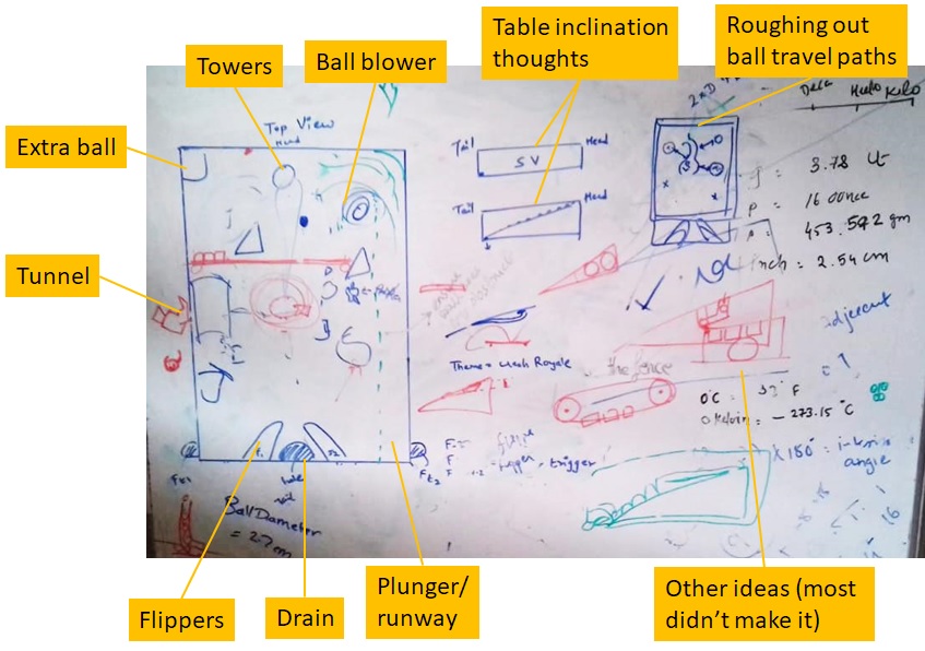
Post this initial working idea, we immediately shifted to an A4 sized paper for further detailing and trying to build a rough blueprint towards making the 1st prototype.
Design:
After a few paper designs we felt confident we had enough cohesive elements to start a little more advanced prototyping. We decided to make it with as simple materials as we could, allowing for fast iterations but at the same time give us a decent idea of game play experience. The result was this:
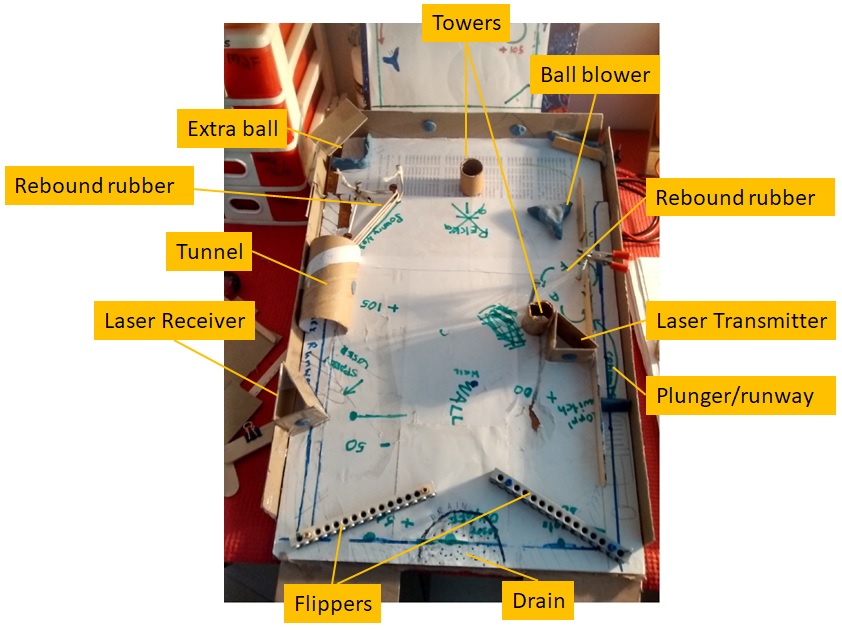
The whole thing had been held together by hot glue, nails/screws (rebound rubber) and children’s clay dough. The intent was to build something that can be ‘played’ so as to get a good idea of key game mechanics like:
-
Is the game board slope good? Does the ball roll forward always and with manageable speed? Too fast and the game becomes too hard to play. Too slow may take away from randomness in the game
-
Are there dead zones in the board? That is, does the ball stop and be stationary at any part of the board? This is not something that should be allowed, obviously
-
Is it possible to hit all the elements in the game? Does the ball ‘treat’ all elements as equals? We don’t want the ball to monopolize one or a few elements
-
Are the flipper angles good? Is the space between the flippers good?
-
Is the drain position good?
-
Does the ball bounce satisfactorily from the rebound rubber? I had tried different materials for rebound rubbers – standard elastic rope - the kind used in clothes wear, natural latex rubber string and a kind of stretchable sewing thread (almost an elastic nylon string)
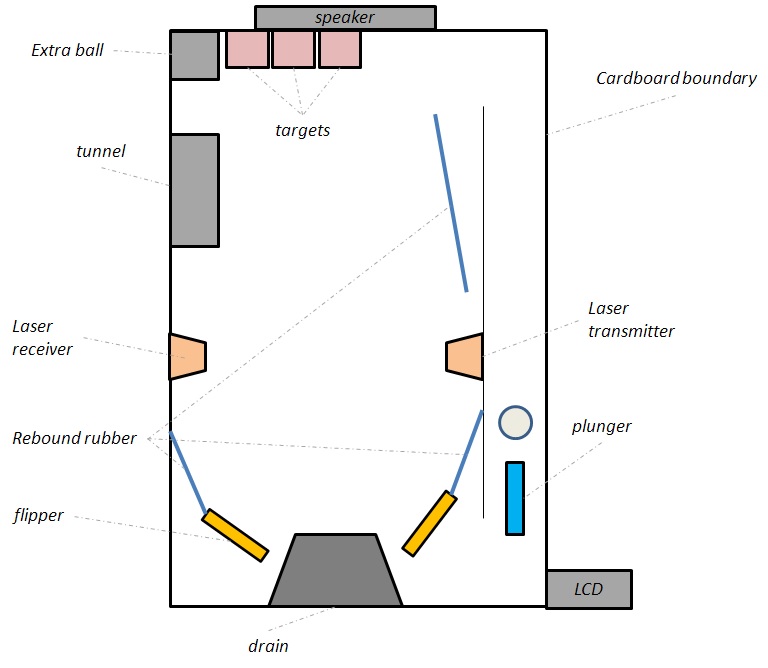
A quick guide to the game elements:
-
Flippers – used to launch the ball back into play up the game board, ideally never allowing it to fall into the drain
-
Plunger – launches the ball at start of play or when a new ball comes into play
-
Drain – where the ball goes to die (!), that is, it goes out of play. Usually, players have limited number of balls to play
-
Laser transmitter/receiver – this would cut horizontally across the board during play and if the ball crossed into the beam, player would lose points
-
Tunnel – a sort of speed breaker that would ensure maximum contact with the laser if the player is out of luck. Also works as a brake for the extra ball
-
Extra ball – at some point in the game, an extra ball is released into the game allowing the player to score more
-
Rebound rubber – works as a randomizer in the game. Once the ball hits the rebound rubber, it can go anywhere and thus injects more variability in the play
-
Towers – the targets. Hitting them gives points to the players
-
Ball blower – A fan or similar that can hit the ball and throw it randomly across the game board. In the final version, we did away with this as it took up too much space and the motor we needed injected too many vibrations on the board
The primary game objective is to score as many points as possible until either time runs out or you run out if balls to play.
Coming back to the prototype board above, once we started playing with it for a couple of days, we learnt quite a few things:
-
Rebound rubber was best with the stretchable nylon sewing thread
-
Flippers must be anchored at the proper angles else they may not have enough leverage to hit the ball with required force
-
The housing location of the various elements must be proper to avoid dead areas
-
The towers need to be at the far end wall rather than where they were in this prototype so that they do not obstruct the ‘flow’ of the ball around the game board
-
The blower was taking up too much space
2nd Prototype:
With these learning’s, we were confident that we could eventually proceed with building the 2nd prototype. The intent for this was to have everything the final board would have including live elements, live scoring and game play. It would also have the LCD and speakers. But before that, we needed to:
-
Familiarize ourselves with some of the components to be used as they were new to us, primarily the vibration sensors and the LED strip (WS2812B)
-
Finalize the anchoring and flexing mechanism for the flippers
-
Finalize the plunger mechanism
The vibration sensors are the 18010p which have both digital and analog outs. The sensor basically registers a hit to itself and provides an output. The digital out threshold is controlled via an on board potentiometer while the analog out feeds out raw hit data. While the circuit for this is pretty simple, we needed to figure out if the hits to the target were registered properly. The image below shows the sensor placed inside a tower target for testing.
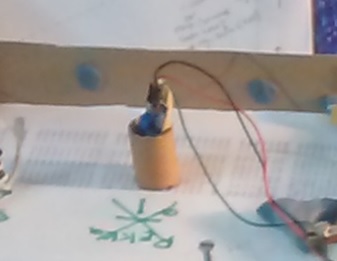
This setup worked OK and the sensitivity was decent enough for hits to be registered on the tower from most directions. However, we figured that the tower placement on the board was problematic as it interfered with the ball flow. Also the shape of the tower made it a little difficult to register hits from acute angles. So, we decided to forgo this tower and instead keep box shaped targets flush with the top boundary wall (as can be seen in the later versions).
For the flippers, the prototype uses nails / screws and Lego parts. We could not, obviously use these in the final version so we designed a flipper with ice cream sticks glued together and used a dremel to drill anchoring holes. The anchor would be a screw while the flex mechanism would be via tension springs. The spring would be attached to the flipper via another screw. The other end of the spring would be attached to a screw driven through the game board. See image below. Apologies for the quality of the photo but I hope you can make out the arrangements. Note the rest of the board of the 2nd prototype. This is start of the prototype which would do everything that the final board would. Also note that in the final board, the flipper design was changed and only one spring was used for each as there was a change to the dimensions of the flipper.
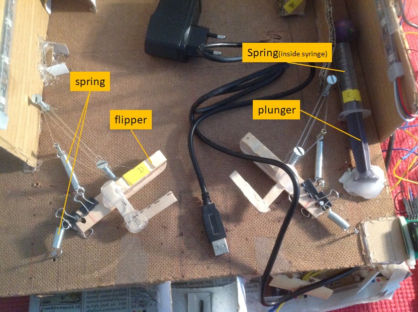
The plunger design was made using a 25 ml syringe. The piston was anchored to the board and the player would depress the syringe and let go to launch the ball. The syringe contains a compression spring inside it.
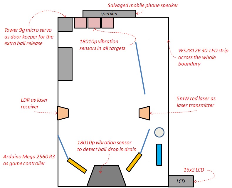
This completes familiarizing ourselves with the unknown components and we went on to build out the full game board for the 2nd prototype. Here is the design for it:
To understand what electronic components were used, here is another image overlaying only the electronic components on top of the above image:
At this point it would be good to take a detour into the game logic. We have all the mechanical and electronic elements in place and now need to form rules for the game play. Here they are:
-
A game runs for 90 seconds or all balls are lost, whichever occurs first. A player gets 3 balls at start to play with (one by one)
-
A target hit nets points. The points incremented are somewhat different for some targets as they are a little harder to hit accurately
-
During game play, an extra ball would be released randomly at any point in time. The player thus, gets a total of 4 balls to play in each game. An extra ball release event also nets bonus points
-
A ball drop is detected in the drain and that decrements the balls available per detection
-
Multiple times in a game, the laser turns on and if the ball passes through the beam, it is detected and points are decremented
Also,
-
Game score, time remaining and balls remaining are displayed on the LCD
-
The speaker plays a game start tone when the game begins and plays a tone for point increment or decrement (each different)
-
For each point increment and decrement the relevant LED’s in the WS2812B strip light up briefly as a visual indication. A number of lights also light up when a ball is lost (drain)
Before we actually delve into the game logic here is the 2nd prototype image
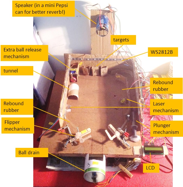
Here is the same image without annotations, for an uncluttered look:
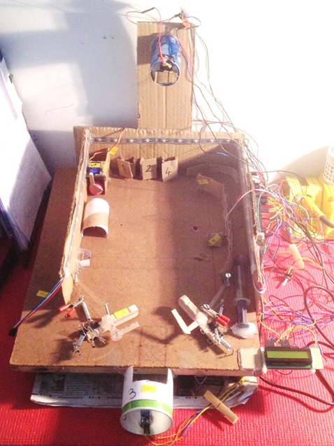
Do excuse the rat’s nest of wires as it’s a prototype! While it looks rickety, it played well enough to finalize the design. Everything worked as expected, more or less, and some learning’s that were found in the 1st prototype applied here too.
Game program logic:
The full source code is available here but the logic flow is explained here via a flowchart.
The main loop (method GameLoop() in the code):
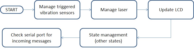
-
Manage triggered vibration sensors – all the 4 vibrations sensors (3 targets and 1 ball drop), are hooked up to the external hardware interrupts of the Mega 2560. Whenever they register a hit, a flag is set for eventual perusal from this function. For the targets, if the flag is set, a hit is counted, points are incremented and the points are updated. Also, the speaker sounds an increment tone and the LED strips flashes the relevant LED’s (blue) aligned to the relevant target. In case of the ball drop, everything as above is repeated except points don’t change and the number of balls available is reduced by one
-
Manage laser – the laser periodically turns on for a set amount of time (5 seconds). It does this multiple times in a game. When the laser is on, the receiver (LDR) registers the laser on it and the analog IN of the Mega 2560 monitors that. If the ball crosses the laser beam when it is on, the Mega detects it via the voltage change on its analog IN pin. This is counted as a point decrement and the points are updated. Also, the speaker sounds an decrement tone and the LED strips flashes the relevant LED’s (red) aligned to the relevant target
-
Update LCD – self-explanatory. Updated the LCD to reflect the current points, time elapsed in seconds and balls remaining
-
State Management (other state) – controls the extra ball release. The ball is released randomly between 15 to 75 seconds of the game. Each iteration of the game, the release time is different. It is calculated at game initialization time and this function merely checks if it is time to release it
There is a lot of other code too and the Setup() method is the one calling that other code. It should be more or less easy to understand but drop me a note if you need something clarified.
Final prototype:
Based on all of the above, the final version was created and is shown here. A video of the game play follows below that.
Video - TBD
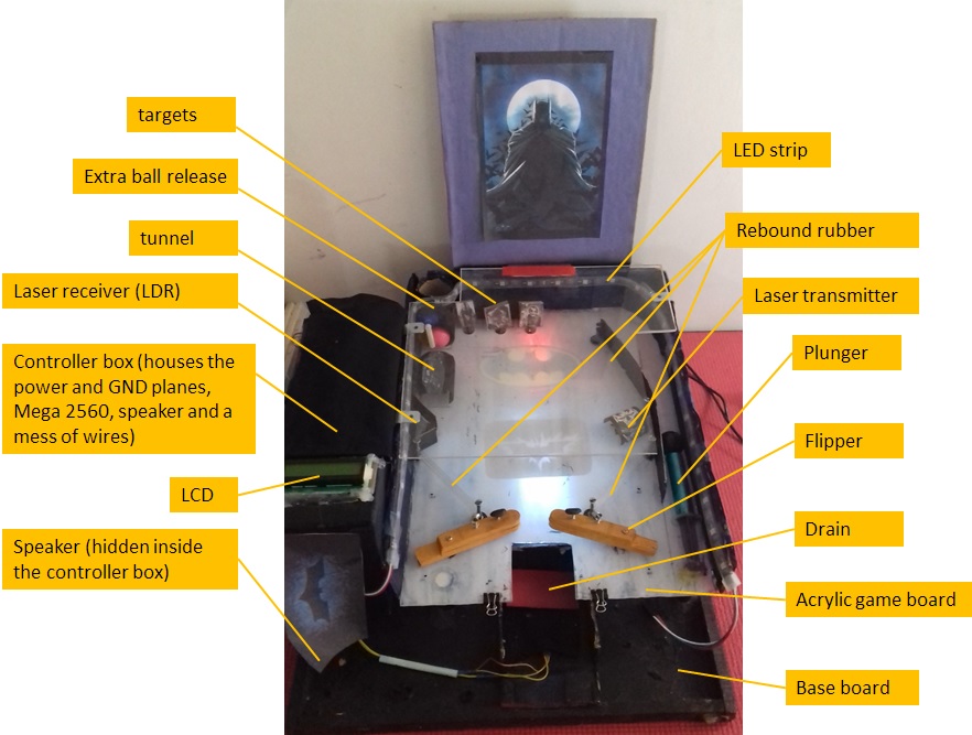
As can be seen, some placements have been changed and a clear theme is present. Based on my son’s preferences, we decided on a Batman theme. The targets (backed by vibration sensors) are Batman villains like Bane, Scarecrow and the Joker (hitting these increment points). The laser is El Diablo (decrement points as you are hit by his fire). The main ball is the Batman spray painted black. The extra ball is designated as the Batmobile and the tunnel is the Batcave. Apart from these, there are some images that have been glued to the game board to give a complete theme feel.
Here are some more pictures of the game with short descriptions to explain better:
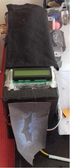
- Close up of the Game controller box and the LCD:
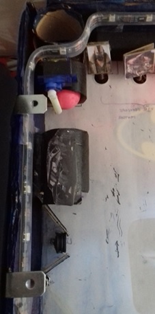
- Close up of laser receiver (LDR), the tunnel and extra ball release mechanism:
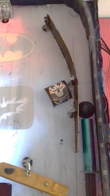
- Close up of laser transmitter, plunger and rebound rubbers:
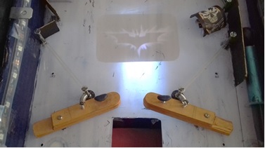
- Close up of flippers, drain and rebound rubbers:
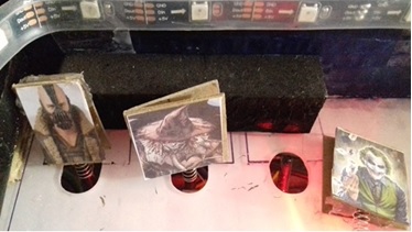
- Close up of targets, with springs to mount them on them on the vibration sensors:
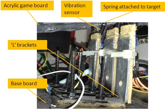
- The image below shows the underside of the game board, where the vibration sensors have been fixed:
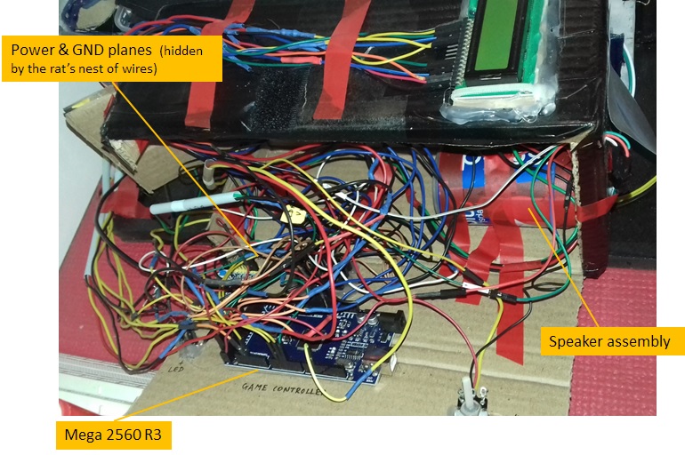
- An image that shows the open game controller box and the mess of wires. Try debugging a loose connection here! (I love pointless challenges!!):
-
In game score lcd pic: TBD
-
Game over lcd pic: TBD
Challenges:
I would also like to discuss some challenges that this project threw up and what I did to meet them.
-
Power supply – the game has a few components that cannot be powered directly through the Mega. The reason for this is their current draw which is usually (on average) more than what the Mega can source. As a side note, always be aware of the current draw of your components and circuit as a whole. Coming back, these components are: the motor fixed for the extra ball release (> 1000 mA at times), the LED strip (up to 1800 mA at full brightness), the speaker (~180 mA) and the LCD screen (~150 mA). Except the speaker, all run at 5V (speaker runs at 3.3V). I purchased one DC +5V 3A power supply adapter and another DC 12V 2A, both of which could directly plug into an AC wall wart (240 VAC, 50 Hz). The LED strip and motor consumed the 5V 3A while the rest consumed the other (via a DC power module that gave me multiple outs of 3.3V and 5V). Of course, everything was tied to a common ground plane. If I had the budget, I would probably go for a SMPS supply that would ensure a single wall wart plug instead of the two I had now. I also had the LED strip dialed down to low brightness which was enough for my conditions.
-
Vibration sensor sensitivity – there was one change that I made from the 2nd prototype to the final prototype which cost me a lot of time. The 2nd prototype game board was made up of particle board while the final one was made up acrylic. I decided on acrylic because I wanted to stick the game theme stickers underneath the board so that they would be fuzzily visible when playing and give a nice effect. The acrylic was also easier to paint and cut. However, I figured out (after much experimentation and testing) that the acrylic was much more sensitive to vibrations and conducts vibrations much better than wood. Every time I would flex the flippers, the vibration sensors on the targets at the far end and the drain beside the flippers would register a hit. This was because the sensors were mounted beneath the acrylic game board and poked through a tight fitting hole on the board onto the play area. This was a show stopper. After much head banging and help from my better half, we decided to mount the target’s vibration sensors on L shaped brackets fixed to the base board instead of the acrylic. We also increased the diameter of the holes through which the vibrations sensors poked through the game board so that they would not touch the acrylic board in any way. This worked well and fixed the issue. We fixed the drain too to the base board not allowing it to touch the acrylic game board in any manner.
-
Extra ball release shaft angle – this was not a biggie like the other two but important enough to ensure that I measure the angle at which the ball would rest against the shaft and not come out. The angle at which the ball would freely roll out was also important.
Improvements:
Also, there are quite a few improvements I would like to get in someday.
-
Demo mode, game start button – the game is currently started by resetting the Mega. I plan to add a game start button and while the game is not playing, a demo mode that would have some nice sound n light show
-
Better packaging / look – the current packaging and finish of the game is just about passable. I would like to refine it
-
LED strip below game board to provide ambience to the game
-
Move laser LDR to pin change interrupt – Currently the LDR analog values are checked in the main loop (called from GameLoop() ). However this slows down the loop end to end time and leaves very little scope for adding further logic. I would want to try out moving the LDR detection to a pin change interrupt to mitigate this
-
Add adaptive gameplay – since this is primarily a game of skill with some element of luck thrown in, it would make sense for the game to adapt to the players. For e.g., good players should see increasingly difficult gameplay and vice-versa. All this is possible by maintaining a player profile or a simpler version that just reacts to the current game in progress
I hope this was interesting to readers. We had great fun making it and watching players’ faces light up when playing! If you have any questions please drop me a message!